Feature
Multi-channel Input
Max 36ch (analog input), Max 144ch (logic input)
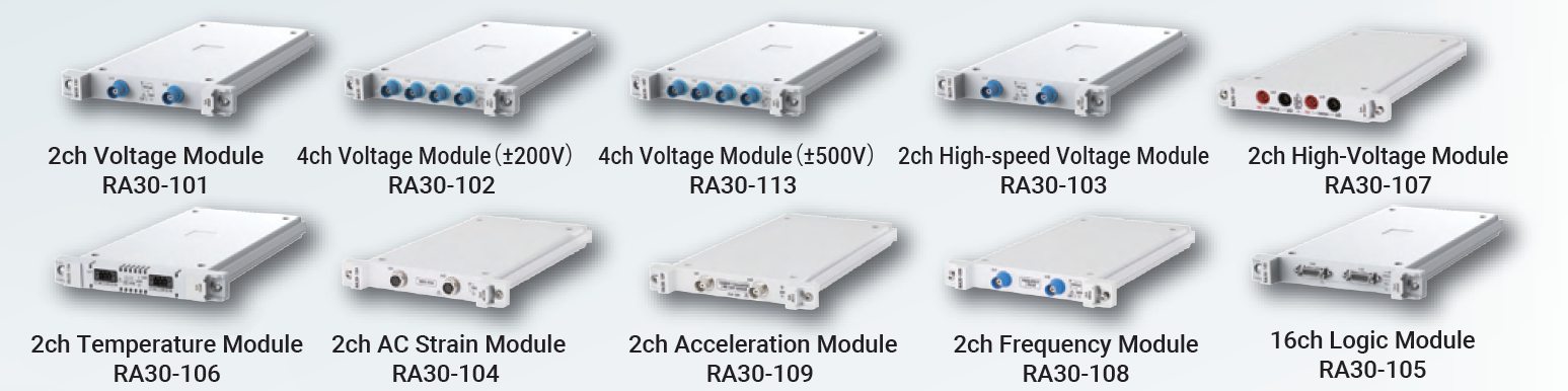
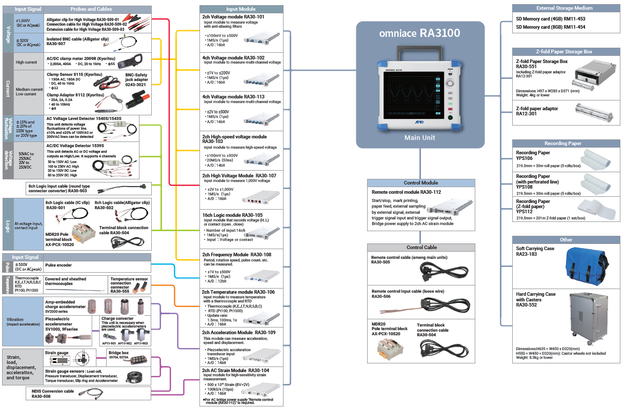
“The 4ch Voltage Module” allows 4-channel input with a single unit. 9 modules can be installed in the main unit, allowing 36-channel recording.
“The 16-channel Logic Module” allows 16-channel logic signal input with a single unit. 9 modules can be installed in the main unit, allowing 144-channel logic signal recording.
High-speed Sampling and High-definition Measurement at 20MS/s with 18ch for 5 seconds
“The 2ch High-Speed Voltage Module” is an input module for high-speed sampling at the highest level of the series. Includes the ability for a sampling rate of 20MS/s, input voltage up to ±500V, and 14bit resolution. 9 modules can be installed in the main unit, allowing for 18-channel high-speed memory recording.
Long-term Recording
Various recording speeds, multiple channels, and a high-capacity storage medium to support a large amount of data are included as standard. Recording desired signal accurately without missing detailed changes.
- Memory capacity of 4GB (when 18 channels are used, 20MS/s, 5 seconds)
- SSD capacity of 256GB (when 36 channels are used, 1MS/s, approximately 59 minutes)
High-speed and High-definition printing
High-resolution waveform printing at high speeds (100mm/s) is possible. Even if the chart paper runs out, recorded data is backed up to the SSD and can be printed out later.
Various Recording Method
The data recording destinations include “memory,” “SSD,” and “printer”. Data recording can be performed at three destinations at the same time. In addition, “pen recorder recording” is also possible, which records data only on recording paper for simplified measurements.
You can freely select depending on the purpose of your measurement.
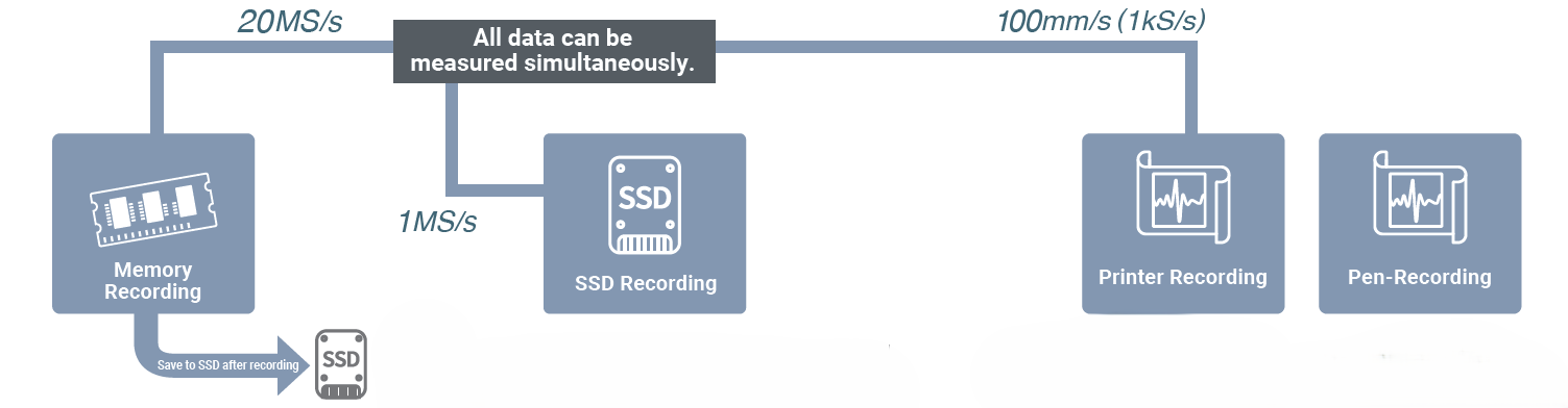
Recording
Memory Recording
Memory mode records data in the internal memory (4GB) at high speed (Max: 20MS/s). In addition, measurement can be performed under a variety of conditions using a variety of trigger functions. After the input data is recorded in the memory, it is automatically saved to SSD.
- Sampling speed: 20MS/s to 10S/min (depending on the input module)
- Memory capacity: 4GB (2G point/ch)
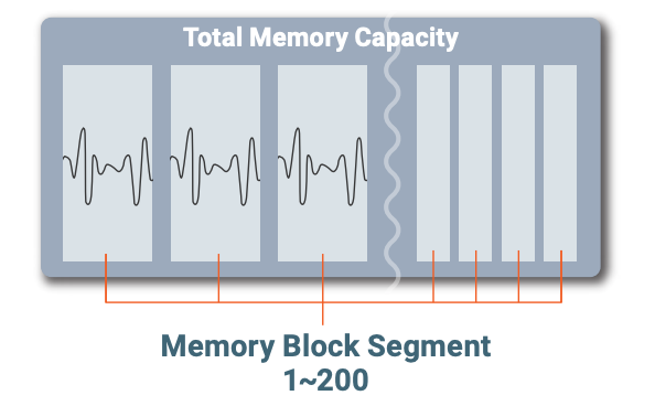
- Memory divisions: 1 to 200 divisions
- Recording length: 2,000 to 2G points/ch (1-2-5 step)
Recordable Time on Memory
| Sample speed |
2ch |
8ch |
18ch |
36ch |
| 20MS/s | 50 sec | 10 sec | 5 sec | – |
| 10MS/s | 1 min 40 sec | 20 sec | 10 sec | 5 sec |
| 5MS/s | 3 min 20 sec | 40 sec | 20 sec | 10 sec |
| 2MS/s | 8 min 20 sec | 1 min 40 sec | 50 sec | 25 sec |
| 1MS/s | 16 min 40 sec | 3 min 20 sec | 1 min 40 sec | 50 sec |
| 500kS/s | 33 min 20 sec | 6 min 40 sec | 3 min 20 sec | 1 min 40 sec |
| 〜 | 〜 | 〜 | 〜 | 〜 |
| 10kS/s | 27 hrs 46 min 40 sec | 5 hrs 33 min 20 sec | 2 hrs 46 min 40 sec | 1 hrs 23 min 20 sec |
| 5kS/s | 55 hrs 33 min 20 sec | 11 hrs 06 min 40 sec | 5 hrs 33 min 20 sec | 2 hrs 46 min 40 sec |
| 2kS/s | 138 hrs 53 min 20 sec | 27 hrs 46 min 40 sec | 13 hrs 53 min 20 sec | 6 hrs 56 min 40 sec |
| 1kS/s | 277 hrs 46 min 40 sec | 55 hrs 33 min 20 sec | 27 hrs 46 min 40 sec | 13 hrs 53 min 20 sec |
SSD Recording
Long-term of data can be recorded to the internal SSD. High-speed recording of up to 1MS/s is possible when using 36ch. Since it is stored as digital data, data can be analyzed after recording and data can be managed for a long period of time. Input data is saved directly to SSD.
- Sampling speed: 1MS/s to 10S/min (depending on the input module)
- SSD capacity: 256GB
- Maximum recording time: 100 days
- Data format: Normal data, Peak data
Recordable Time on SSD *1
| Sample speed |
2ch |
8ch |
18ch |
36ch |
| 1MS/s*2 | 11 hrs 46 min 40 sec | 3 hrs 55 min 33 sec | 1 hrs 51 min 34 sec | 57 min 17 sec |
| 500kS/s | 23 hrs 33 min 21 sec | 7 hrs 51 min 07 sec | 3 hrs 43 min 09 sec | 1 hrs 54 min 35 sec |
| 200kS/s | 2 day 11 hrs 20 min 02 sec | 19 hrs 37 min 48 sec | 9 hrs 17 min 54 sec | 4 hrs 46 min 29 sec |
| 100kS/s | 4 day 21 hrs 46 min 49 sec | 1 day 15 hrs 15 min 36 sec | 18 hrs 35 min 48 sec | 9 hrs 32 min 59 sec |
| 50kS/s | 9 day 19 hrs 33 min 39 sec | 3 day 06 hrs 31 min 13 sec | 1 day 13 hrs 11 min 37 sec | 19 hrs 05 min 58 sec |
| 20kS/s | 24 day 12 hrs 54 min 09 sec | 8 day 04 hrs 18 min 03 sec | 3 day 20 hrs 59 min 04 sec | 1 day 23 hrs 44 min 55 sec |
| 10kS/s | 49 day 01 hrs 48 min 19 sec | 16 day 08 hrs 36 min 06 sec | 7 day 17 hrs 58 min 09 sec | 3 day 23 hrs 29 min 51 sec |
| 5kS/s | 98 day 03 hrs 36 min 38 sec | 32 day 17 hrs 12 min 12 sec | 15 day 11 hrs 56 min 18 sec | 7 day 22 hrs 59 min 43 sec |
| 2kS/s | 100 day | 81 day 19 hrs 00 min 31 sec | 38 day 17 hrs 50 min 46 sec | 19 day 21 hrs 29 min 19 sec |
| 1kS/s | 100 day | 100 day | 77 day 11 hrs 41 min 33 sec | 39 day 18 hrs 58 min 38 sec |
| 500S/s | 100 day | 100 day | 100 day | 79 day 13 hrs 57 min 16 sec |
| 200S/s | 100 day | 100 day | 100 day | 100 day |
*1 If you select peak data as the data type, the time will be 1/2 of the above time.
*2 A sample rate of 1 MS/s is not available when peak data is selected as the data type.
Window Recording
Endless recording is possible by specifying the ring buffer area (maximum 2G points/ch) as the window recording time. If you do not know when an abnormality will occur, you may miss the abnormal data if you set the recording time and measure. By ringing the recording area, you can always save the latest data.
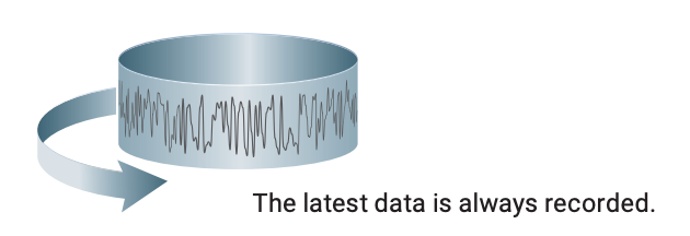
Selectable for SSD Recording
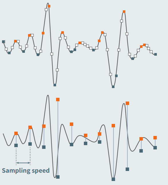
Omniace is a digital recorder that performs analog to digital conversion on all inputs and records those signals. Due to the relationship between the speed of analog to digital conversion and the frequency component of the input signal, the data may or may not be measured correctly.
Normal Data
Normal data is recorded at each designated sampling speed. (□ points) If the signal changes too fast relative to the sampling speed, the data singular point (peak value) may not be recorded. Memory recording can measure this type of data.
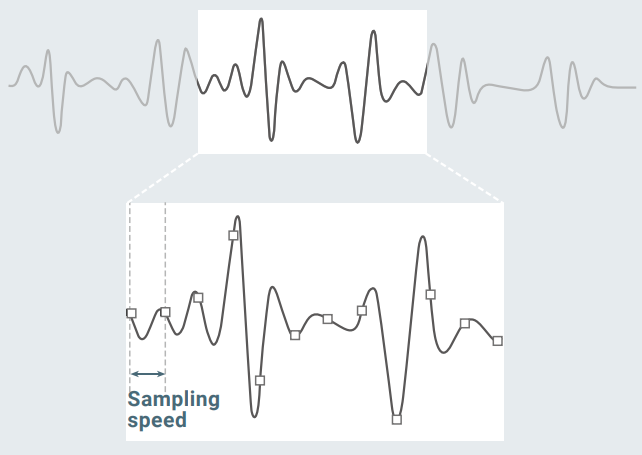
Peak Data
Peak data is sampling (■, ■, and □ points) between the designated recording speed at the fastest AD-conversion rate, and records two data points, the maximum value (■ points) and the minimum value (■ points). The amount of data can be compressed without losing the data singular point (peak value). Printer recording records data of this method on the chart paper.
Printer Recording (Pen-Recording)
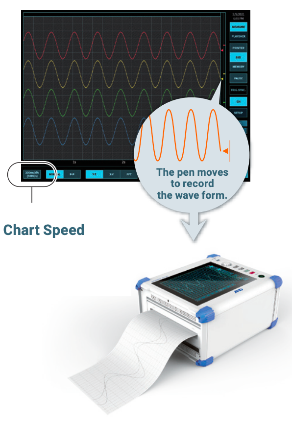
Input data is printed directly on the chart paper at high speed (MAX 100 mm/s). Data printed on chart paper is also stored digitally on the SSD, so even if the chart paper runs out, the data can be printed out later.
Pen-Recording
Pen records are only recorded on recording paper; measurement data is not stored. Input module and paper feed rate settings can be configured during recording.
Recording Specifications
- Number of recorded signals: 48 channels
- Chart speed: 100mm/s (1kS/s) ~ 1mm/min (10S/min)
- Recording resolution: 20 to 80dots/mm (time axis), 8dots/mm (amplitude axis)
Display
Excellent Visibility and Operability
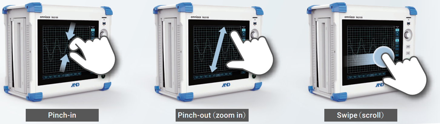
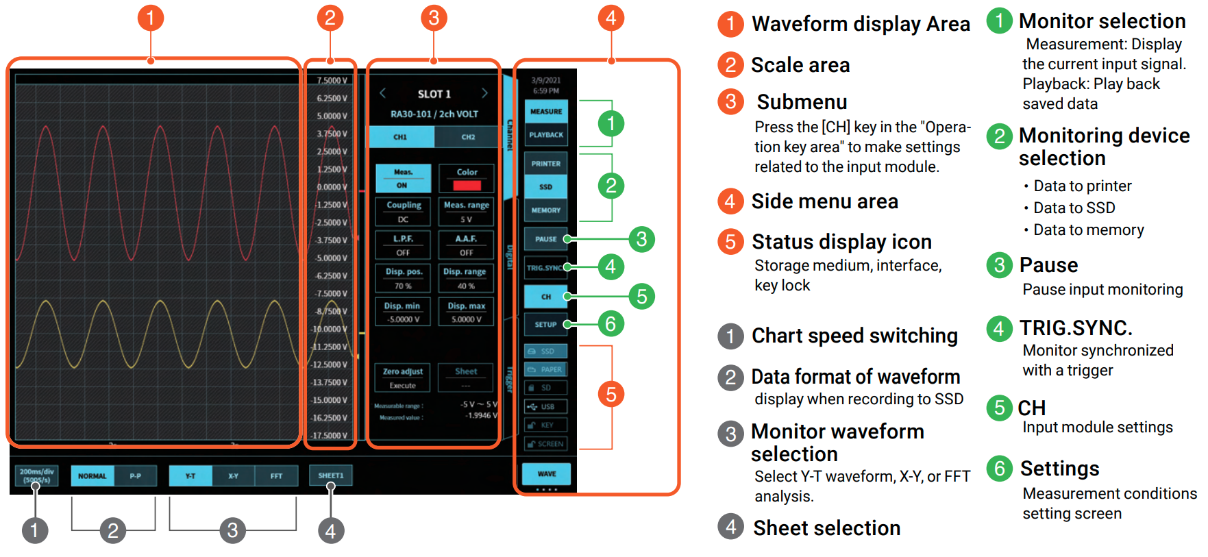
The LCD display with touch panel allows zoom in and out, and scrolling through the waveform simply, allowing a dynamic waveform drawing and operability like a smartphone. Pinch-in, Pinch-out, Swipe.
Back scrolling
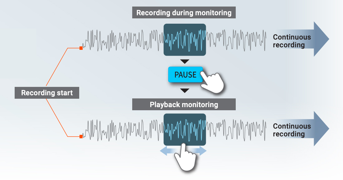
Press the [PAUSE] button during recording to playback recorded data while recording. Recording start, Recording during monitoring, Playback monitoring, Continuous recording.
Various Monitor Displays
Input signal and recorded data can be displayed as Y-T waveform display, X-Y waveform display, and FFT.
Y-T Waveform Display
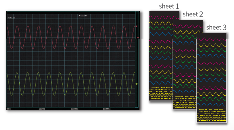
Display the measurement channels split into three sheets. Monitors up to 48 channels of signals on a sheet with 20 divisions in vertical and horizontal. Graphs can be divided into 1 to 18 sheets and displayed.
Set the signal display width and display position
Signals can be drawn at any position on the graph at any width. You can easily draw a 100V signal in the width of 1div.
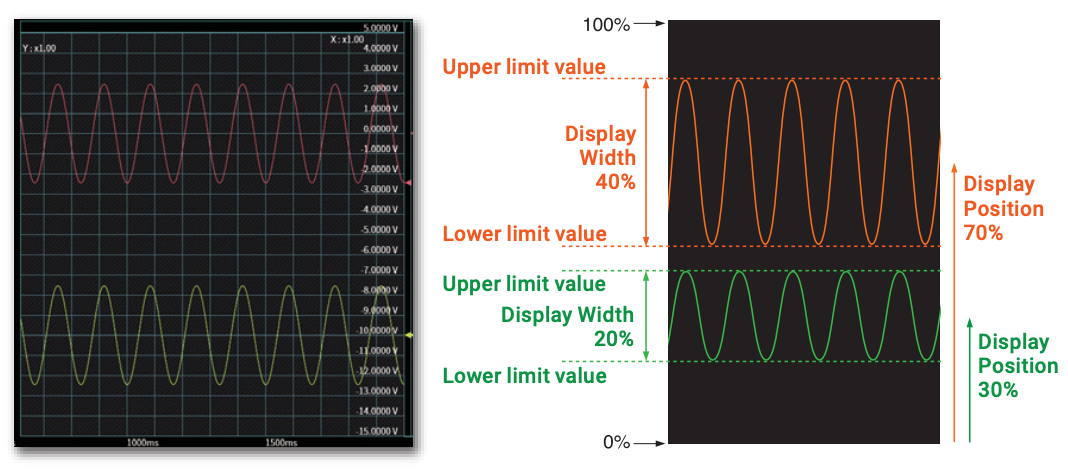
- Display Width — Display the signals of each channel at any width. Set the width of the channel to be displayed as % out of the 100% width of the display graph.
- Display Position — Set the position of the channel to be displayed as % out of the 100% width of the display graph.
- Scale Setting — Set the upper limit/lower limit value of display for the display width of each channel as an input value or a physical conversion value.
X-Y Waveform Display
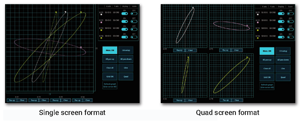
An X-Y screen format can be drawn by specifying 4 channels for the X-axis and 4 channels for the Y-axis. The graph can be displayed a large single screen format, or divided four screen format for the each X and Y axis channels. The pen can also be moved up or down, and the grid can be turned on or off.
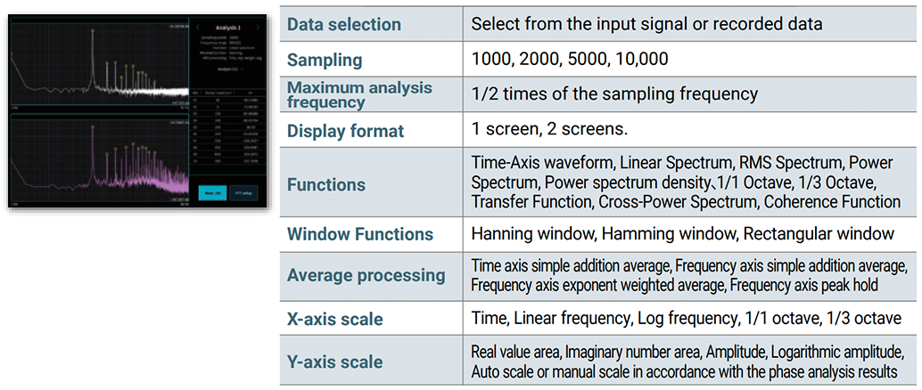
FFT Analysis
FFT analysis is performed for any two signals. The top 10 highest values can be read from the analysis results, and the value of any analysis result can be read using the cursor. (FFT analysis can be performed on normal data recorded in SSD.)
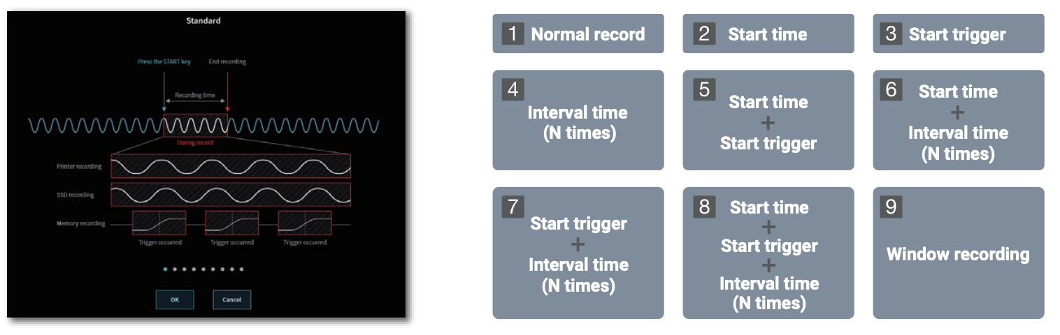
Recording Mode Selection
Nine measurement patterns are prepared as recording modes. “Recording Mode” can be selected from Measurement starts by manual operation, Measurement starts from a trigger signal or Repeating measurement, etc. When “Recording Mode” is selected, the necessary set-up menu is displayed and can be easily set.
PC Compatibility
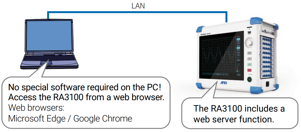
Web server, FTP server
The RA3100 can be remotely operated from a web browser (operating PC). The web browser displays the same screen as the RA3100 main unit with pseudo operation panel keys (START key, etc.) to make settings and start/stop recording. Additionally, data stored on the RA3100 can be transferred to a PC.
Software for displaying measurement data *3
“RA3100 Viewer” is software to display recorded data exported to external media from an RA3100 on a PC.
PC software for converting measurement data *3
The “File Converter” software can convert recorded data exported to external media from an RA3100 to CSV or ASAM MDF (Ver. 4.1) files on a PC.
*3 The software can be downloaded from our website: https://www.aandd.co.jp/support/soft_download/industrial.html

 Brochure